Firing positions are used to indicate where on the screen your effects will fire from. Each position is assigned a name and location, then each effect in your show is assigned to one of these positions. A position can be located anywhere in the scene, and there is no limit to how many positions can be created. When the “View Positions” option is checked in the position menu seen in Figure 1, all firing positions will be visible in the simulation windows as arrow markers with the position names listed under them. Clicking on these markers while scripting a show will select or deselect them, depending on what state they are in when clicked. A red arrow indicates a selected position, and any effects added to the show will assign these positions to the cues when created. If more than one position is selected, then a cue will be created for each position. The position markers will hide themselves when playing a simulation, but you can also hide them while scripting by unchecking the “View Positions” option in the position menu.
The Position Editor is where all settings for each position are made, which includes the position name, location coordinates and optional tilt and pan angle values. This editor is also accessed from the position menu shown in figure 1. When creating a new show, you will automatically be presented with the position editor as the second step in creating the show (the first step is filling out the details on the Show Settings screen). A single position will automatically be created for new shows, since at least one position must exist for any given show.
The Position Editor control panel is shown in Figure 3. Positions can be moved around or renamed even after effects have already been assigned to them, although positions with effects assigned to them can not be deleted until the effects are removed.
Adding Positions
Clicking the Add button will create a new position on the screen, with the new position also appearing in the position list. A default name will be created for the position such that it is not a duplicate of any existing position names, since each name must be unique. You are also free to change the name to anything you want using the Name field.
Selecting Positions
To modify the data for any position, it must first be selected. Selected positions are indicated as red arrows, while unselected positions are green. There are two ways to select a position: clicking on it in the position editor list or clicking on its arrow marker on the simulation screen. Note that you can select more than one position at a time, which then allows you to change the location or angle values of many positions at once. If you need to relocate a group of position markers but keep their relative distances from each other the same, you can simply select them in the list and then move them as a group. Changing any position or angle data in the position editor will apply the new value to all selected positions. Note that the name value can not be changed when more than one position is selected, since each position must have a unique name.
When selecting positions by clicking on them with the mouse in the simulation screen, each click will toggle the position arrow between the selected and unselected state. When you click on an unselected (green) position, whichever position was previously selected (red) will become unselected as the new arrow becomes selected. If you need to select more than one position at the same time, you can hold down the shift key to keep previous selections from becoming deselected.
Moving Positions
Each firing position is specified as a set of X,Y,Z position coordinates and two angles. Like models and lights, the positions can be moved around by first selecting one in the list or clicking on one of the green arrow markers to make it active, then holding down the left or right mouse buttons and dragging the mouse. Alternately you can enter in the location coordinates into the text boxes, which represent either feet or meters measured from the center point of the display area. When dragging a position marker, it is not necessary to place the mouse cursor directly on the arrow marker. In fact, if you do that you might accidentally unselect the marker when you click the mouse buttons to initiate the drag. Instead it is best to just click anywhere else on the screen and the position marker will still follow the mouse movement.
Note that the checkbox next to the position coordinates must be checked in order to move positions using the mouse. Since the mouse is normally used to move the viewpoint when holding down its buttons and dragging on the simulation screen, this checkbox is used to indicate that you want to adjust the position and not the viewpoint. If the box is not checked, then mouse movements will adjust the viewpoint instead.
Firing Angles
The Angle field represents a deviation from the straight up position specified in degrees. The values you enter will correspond to the angle notation preferences you have setup in the Program Settings screen. For example, if you are using positive angles to tilt the mortar to the right, negative tilting to the left and zero being straight up, then you would enter 45 to tilt the position right by 45 degrees. This accomplishes the same thing as the Tilt Angle column in the Script Editor, except it will angle the position marker and always fire everything assigned to that position at the specified angle. This is useful when all your shots for a given position will always be at the same angle, such as positions along the side of a building that will fire horizontally. Rather than have to enter 90 degrees for the Tilt Angle column in the script for every shot, you simply tilt the position itself and then leave the Tilt Angle column set to zero instead.
Note that the tilt angle column in the Script Editor still has an effect on positions that are already tilted however. The Tilt Angle values will be added onto whatever the Angle the position is set to, so if you have a position angled 45 degrees in the Position Editor and then use a Tilt Angle of 10 degrees in the script, the actual firing angle will sum these two values together for a final shot angle of 55 degrees.
The Direction angle spins the marker around the vertical axis and is the equivalent to the Pan Angle column of the Script Editor. Like the Pan Angle, this value only has a visible effect if the Angle is not pointed straight up. A small flat sticking sideways from the position markers helps visually indicate the direction angle when looking at the position markers from above. When the direction angle is set to zero, the flag points to the right. As the position angle is increased, the flag will rotate in a clockwise direction. As with the Angle field, Pan Angles used in the Script Editor will be added onto the value of the Direction specified for the firing position when determining the final shot angle. A typical application for when to use the direction field would be when setting up positions around the perimeter of a circular structure such as the rim of a stadium or lake. In these cases the pan angles would typically be the same for every shot at each position, so it makes more sense to specify them in the position editor rather than having to type in Pan Angle values for every shot in the show. This also makes it easier to fine tune the angles after the show has already been scripted without having to edit the script itself.
Reference Markers
Normally the coordinates of each firing position are specified in feet or meters as measured from the center point of the display area. If you would like a firing position to be measured from some other reference location, you can create a reference marker to mark the point where measurements are taken from. This can be useful if there is a landmark at the site such as a tree or other object that you will use as a reference point when actually setting up the mortar layouts on the real shoot site. Normally this feature would not be used very often, but might help when trying to accurately model a shoot site without some kind of ground layout map to use as an overlay. Typically images from Google Earth are captured, scaled and then used as a floor surface in the simulator to guide the placement of firing positions, which is really the preferred method. The reference marker feature was created before this practice was known and is actually a bit obsolete at this point.
To create a reference marker, choose the Reference Marker option from the option listing located above the position list. This will replace the position list with a listing of all markers that have been created.. Creating reference markers is very similar to creating firing positions and the parameters look the same. When a position is created, a blue crosshair marker will appear in the display area to indicate where the marker is set. You can then move this marker around to the correct reference point.
Once your reference marker is created, you can then select the name you gave to it from the Reference listing on any given firing position. When a reference point is selected for a given firing position, the position coordinates will be measured relative to the marker rather than relative to the center point of the 3D simulation space.
Deleting Positions
To delete a position that is no longer needed, simply select its select its name in the position list, then click the delete button. Note that positions which have effects assigned to them can not be deleted. You would first have to remove all effects from the position using the Cue Editor, then return to the Position Editor to delete the position.
ShowSim does not allow you to delete all firing positions, as there must be at least one firing position present in any show. Thus deleting the last firing position is not allowed.
Position Tool Bar
The button bar under the position list has a number of automated features which help with the alignment and placement of multiple positions. Figrures 4 through 6 show examples of how these buttons effect a group of selected cues. From left to right, the buttons are as follows:
Equalize Horizontal Spacing—makes the horizontal space between each selected position equal
Equalize Vertical Spacing— makes the vertical space between each selected position equal
Align Horizontally— aligns the positions even along a horizontal plane
Align Vertically— aligns the positions even along a vertical plane
Rotate— mouse is used to rotate the positions around the center point
Toggle Top View— used to quickly switch between the top viewpoint
Undo—rolls back the last operation when possible
Position Front Creator
The controls under the button bar can be used to create a line of equally spaced positions and optionally fan out the firing angles. Figure 6 shows how a single cue is first selected as the left hand side of the front that will be generated, then the number of firing positions, maximum fan angle and distance between positions are specified on the form. When the \|/ button is clicked it will then automatically generate and place the positions.
Once all positions have been created or edited, click the Done button to save them. If you click the Cancel button then all changes will be lost, so be careful not to click the wrong button.
Page 1
|
|

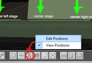
Figure 1:
Accessing the firing position editor from the tool bar.
Figure 1:
Accessing the firing position editor from the tool bar.
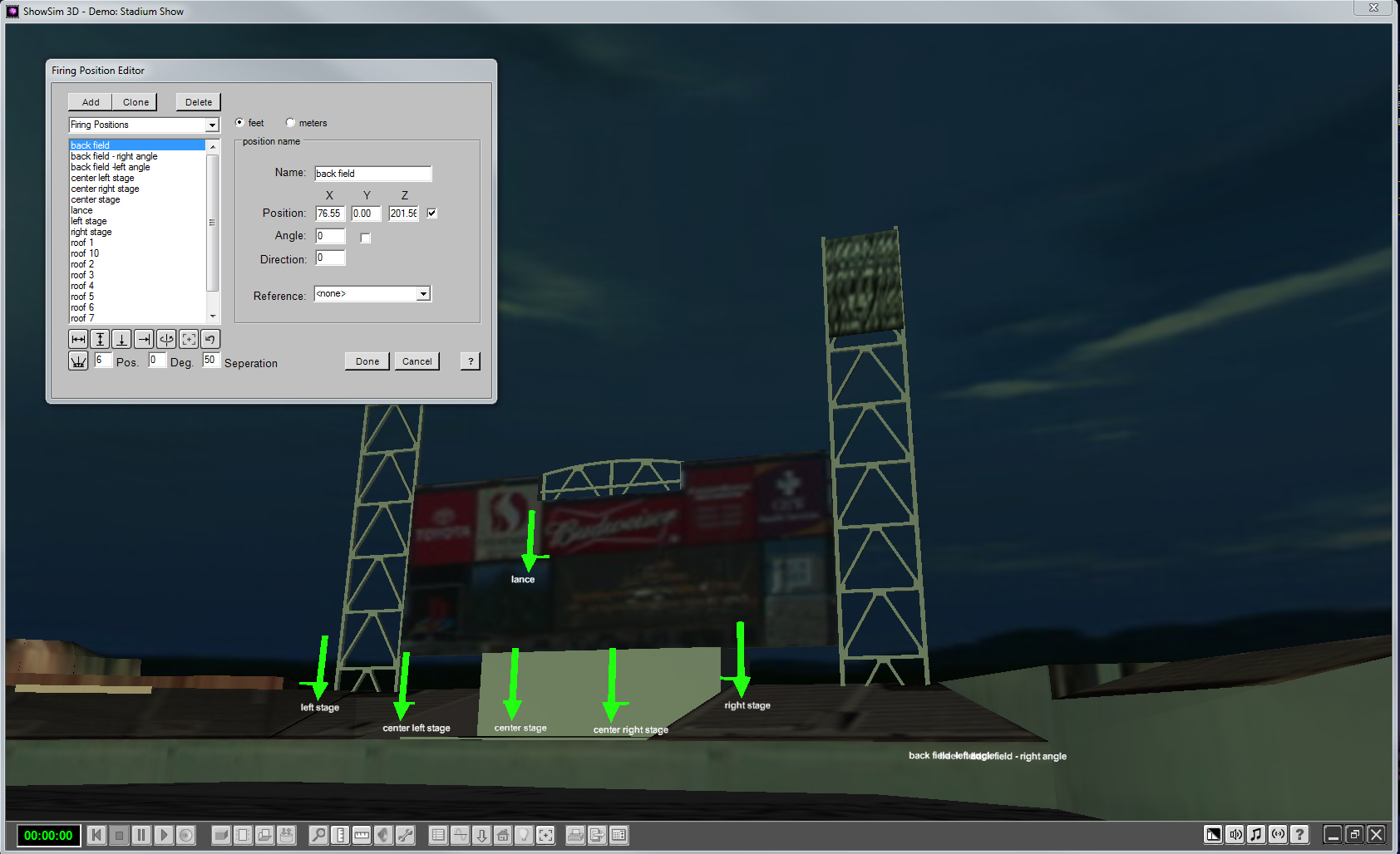
Figure 2:
Editing firing positions.
Figure 2:
Editing firing positions.
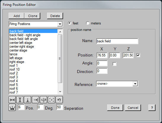
Figure 3:
The Firing Position Editor
Figure 3:
The Firing Position Editor
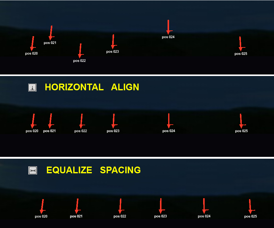
Figure 4:
Adjusting the horizontal alignment and spacing of selected cues.
Figure 4:
Adjusting the horizontal alignment and spacing of selected cues.
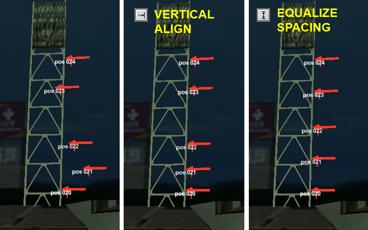
Figure 5:
Adjusting the vertical alignment and spacing of selected cues.
Figure 5:
Adjusting the vertical alignment and spacing of selected cues.
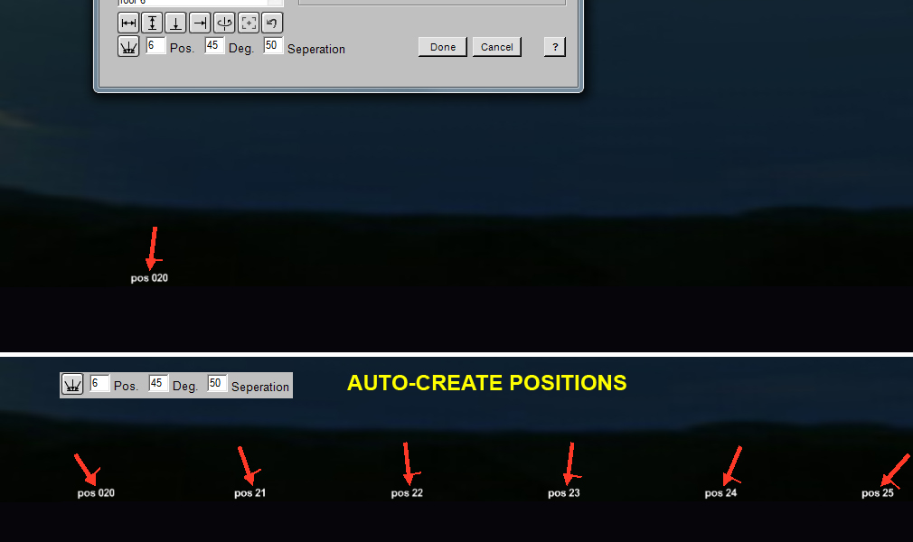
Figure 6:
Automatic creation of position groups with control over spacing and fanned angles.
Figure 6:
Automatic creation of position groups with control over spacing and fanned angles.
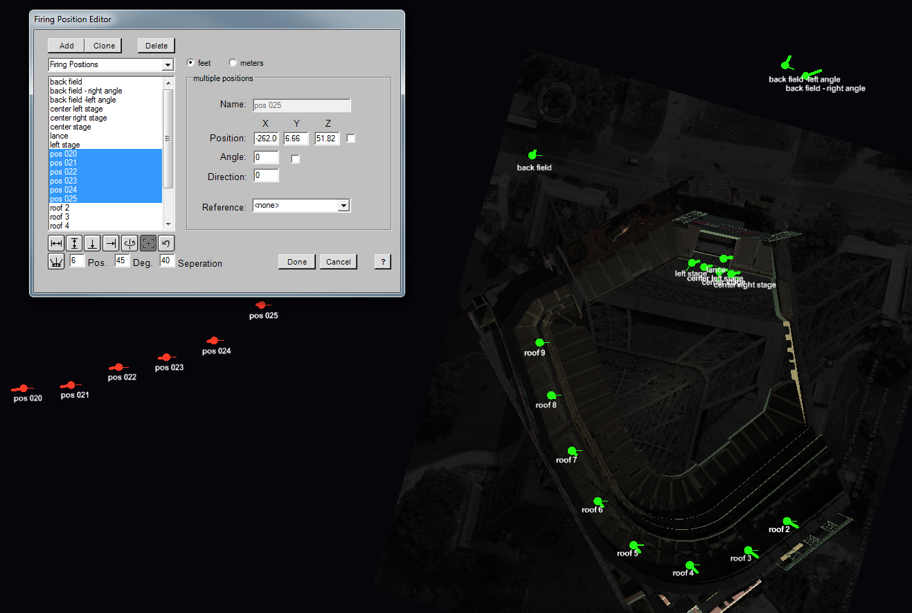
Figure 7:
Using the top view toggle button to switch between birds-eye view of position layout.
Figure 7:
Using the top view toggle button to switch between birds-eye view of position layout.
|
|