The Program Settings window is accessed from the settings menu seen in Figure 1. The settings on this form, which is seen in Figure 2, allow you to specify some general settings that apply to all areas of ShowSim. The details of what each setting does is discussed below.
Language
The Language settings allows you to choose from several major languages that can be used to display all the text elements used in the program. The choices here currently include English, French, Italian and Spanish. To change the language, you must click the Apply button and then restart the program for the setting to be fully applied to all screens.
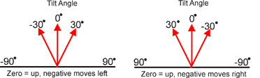
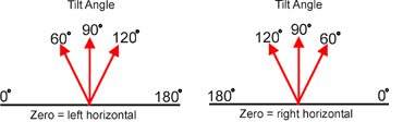
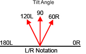
Angle Notation
The angle notation allows you to choose from several naming conventions that can be used to specify angles when scripting. The angle notation will also be used to display angles in the printed reports as well. Some display operators like to notate a mortar that fires straight up as being zero degrees, then any degree to the left or right of this is specified as an offset. Others like to use the standard polar coordinate system where straight up is 90 degrees. ShowSim gives you the flexibility to use whatever notation you are used to rather than force you to convert to what the program itself uses. The images below show how each different option in the notation drop-down list corresponds to the actual mortar angles. Left and right angles of 30 degrees from vertical are used for all example images.
After applying the angle notation the Script Editor will immediately refresh to display the new notation, thus it is not necessary to restart the program.
Default Units
The default units setting allows you to chose between Metric and English measuring systems to be used when displaying size, distance and weights in ShowSim. Note that both the Script Editor and Inventory Editor have a local unit setting that can be used to override this setting, and the Show Settings for each show also has it’s own unit setting that will override the setting specified here. This is just a default setting that will preset the units to the type specified by default, so you would set it to the units that you most commonly use.
Max Shell Drift
When the simulator fires an effect from a mortar during a simulation, there is a random amount of drift to the left or right that is added each time in order to simulate the Magnus Effect that causes shells to arc out of their original trajectories in real life. The shell drift value specifies the maximum range of allowed drift from side to side, which is measured as an offset from the angle that the shell was fired at. So if a shell is fired straight up, then a max shell drift of 30 would mean the most the random drift generator could ever change the trajectory is by 15 degrees to the left or right (with the total span adding up to 30 degrees) as seen in Figure 3. Note that each effect also has a drift specification in the Shell Editor that can be used to control drift on a per-shell basis. What the drift limit on this form does is set a maximum value that can not be exceeded by any of the local drift values specified in the effect editors. The main stock effect library included with ShowSim uses a drift value of 30 for most of the shells. Some people find this value too high for their liking, especially when trying to make fronts using comets which typically don’t have as much drift as a shell would. Rather than having to edit the drift value on every shell to reduce its value, you can simply reduce the max drift value here and it will set a limit on every effect across the board. Note that it can not be used to expand the max drift beyond what is used in the shell editor however, so a value of 40 would not override a value of 30 specified in the shell editor. It can only be used to reduce drift beyond what is assigned in the shell editor.
Figures 4 and 5 show how max drift can affect comet fronts. When max drift is set to zero, the comets will stay on the same trajectory they were fired at, which will give the most defined patterns. With a high drift value such as 30, Figure 5 shows how the comets will randomly deviate from their scripted firing angles and add a degree of randomness to the firing pattern. Thus if your show has a lot of fancy effect fronts that involve comets, you can increase the precision of the patterns by reducing the max shell drift to a low value or even zero.
Page 1
|
|

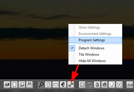
Figure 1:
The settings menu button located on the main button bar.
Figure 1:
The settings menu button located on the main button bar.
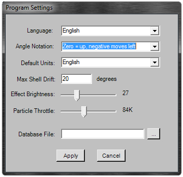
Figure 2:
The Program Settings window.
Figure 2:
The Program Settings window.
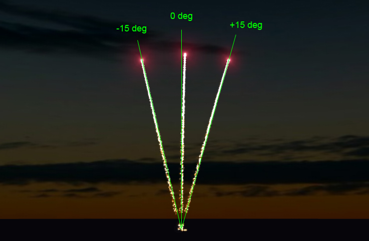
Figure 3:
The maximum range of drift for a comet with a max shell drift value set to 30 degrees.
Figure 3:
The maximum range of drift for a comet with a max shell drift value set to 30 degrees.

Figure 4:
A front of parallel comets when max drift is set to zero degrees.
Figure 4:
A front of parallel comets when max drift is set to zero degrees.
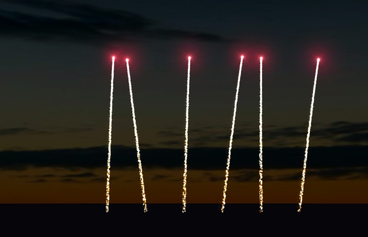
Figure 5:
A front of parallel comets when max drift is set to 30 degrees.
Figure 5:
A front of parallel comets when max drift is set to 30 degrees.
|
|